Introduction
This presentation explores how model-based definition, model-based characteristics, and QIF can unlock enterprise efficiency.
My name’s Evan Kessick. I’m the Director of Model-Based Initiatives at Elysium. I’ve got a wide range of experience in model-based definition and model-based enterprise, and I’m heavily involved in industry standards.
Fred Constantino and I gave an ASME update on ASME model-based standards. I chair the model-based enterprise committee for ASME, co-chair the MBE and Y14 harmonization committee, and am also part of the DMSC.
This Elysium presentation introduces model-based definition, explains its role within the enterprise, and outlines how model-based data supports downstream workflows.
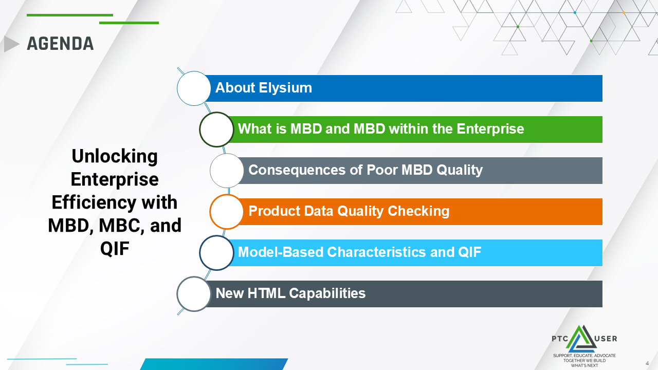
The core topics include the consequences of poor MBD quality, product data quality checking for downstream consumption, data traceability with model-based characteristics and QIF, and the role of HTML-based deliverables.
Elysium is a global software company focused on 3D model-based interoperability. We’re headquartered in Hamamatsu, Japan, with facilities across the United States and Germany. We have over 40 years of CAD data interoperability experience, including model-based definition, and we have strong partnerships with our CAD and PLM vendors, including PTC Creo and Windchill.
We specialize in model-based digital capabilities and have three platforms. Today, we’re primarily going to be talking about 3D-SUITE, which is focused on model-based workflows. We also have CADfeature, which supports CAD migration, and InfiPoints, which supports point cloud handling.
For more information, visit the Elysium booth near the front entrance.
Elysium’s Role in Model-Based Digital Transformation
Elysium supports model-based workflows by providing tools that help organizations prepare, validate, translate, and consume 3D model-based data across the enterprise. A major focus is performing quality checking upfront in the engineering domain, before data is released to downstream users, so teams can confirm that model-based definition data is complete, standards-compliant, and fit for use. The platform supports data translation between native CAD systems such as Creo Parametric and neutral or standard formats including QIF, STEP, JT, 3D PDF, and HTML.
It also supports validation between source and target data to help ensure that important geometry, PMI, presentation states, attributes, metadata, and characteristics remain intact throughout the process. By combining translation, validation, technical data package generation, and downstream deliverables, Elysium helps create a traceable digital thread from engineering into manufacturing, quality, metrology, and other consumption domains. Emerging industry work around model-based characteristics further strengthens this traceability by connecting native Creo data to QIF and enabling bills of characteristics that can be reused downstream.
Within 3D-SUITE and CADfeature, Elysium provides advanced translation capabilities for major CAD formats, including Creo. CADfeature is designed for data migration use cases, such as converting SOLIDWORKS data into Creo while preserving the feature tree so the final model remains editable.
The platform also supports standard and neutral CAD formats, including HTML, 3D PDF, JT, QIF, STEP 214, STEP 242 for model-based definition, and other formats.
What Model-Based Definition Means for the Enterprise
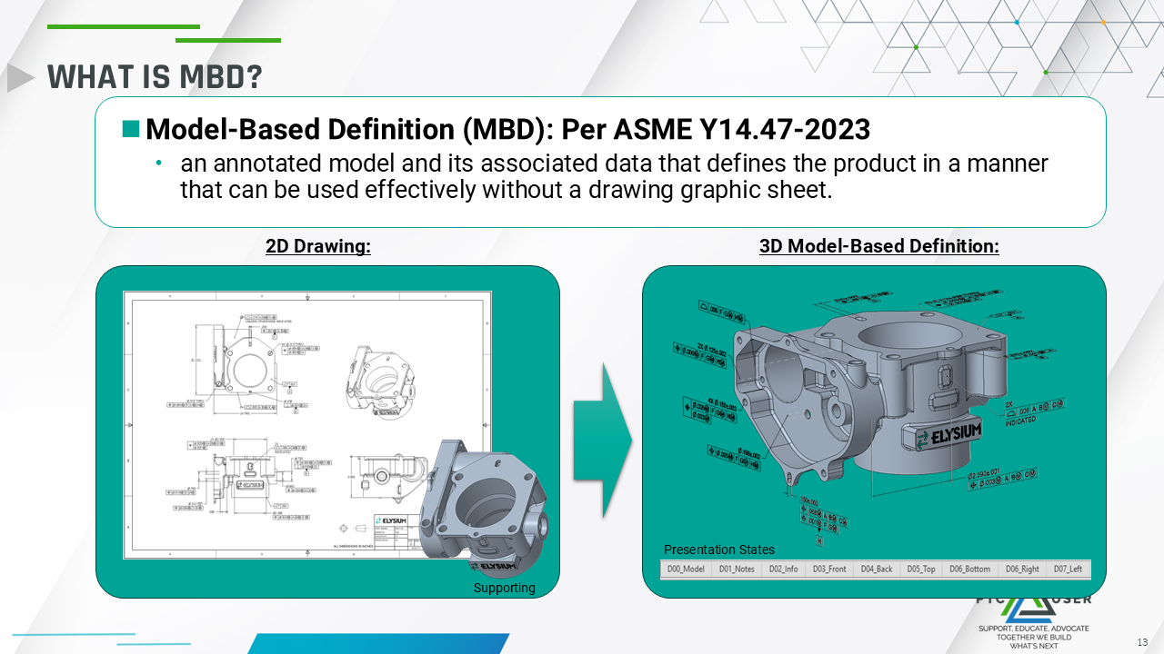
Model-based definition, as described in ASME Y14.47, is an annotated model that communicates product definition without relying on drawing graphic sheets or 2D drawings. Instead, dimensions and tolerances are embedded directly in the model and communicated through presentation states, making the model the authoritative source of product definition for the enterprise.
When discussing product data quality, it is important to focus on the key elements of MBD: geometry, annotations, presentation states, attributes, metadata, and characteristics. Geometry is well established, while annotations and presentation states are increasingly important in digital transformation. Attributes and metadata enable machine readability, and characteristics help connect requirements to downstream quality and manufacturing workflows.
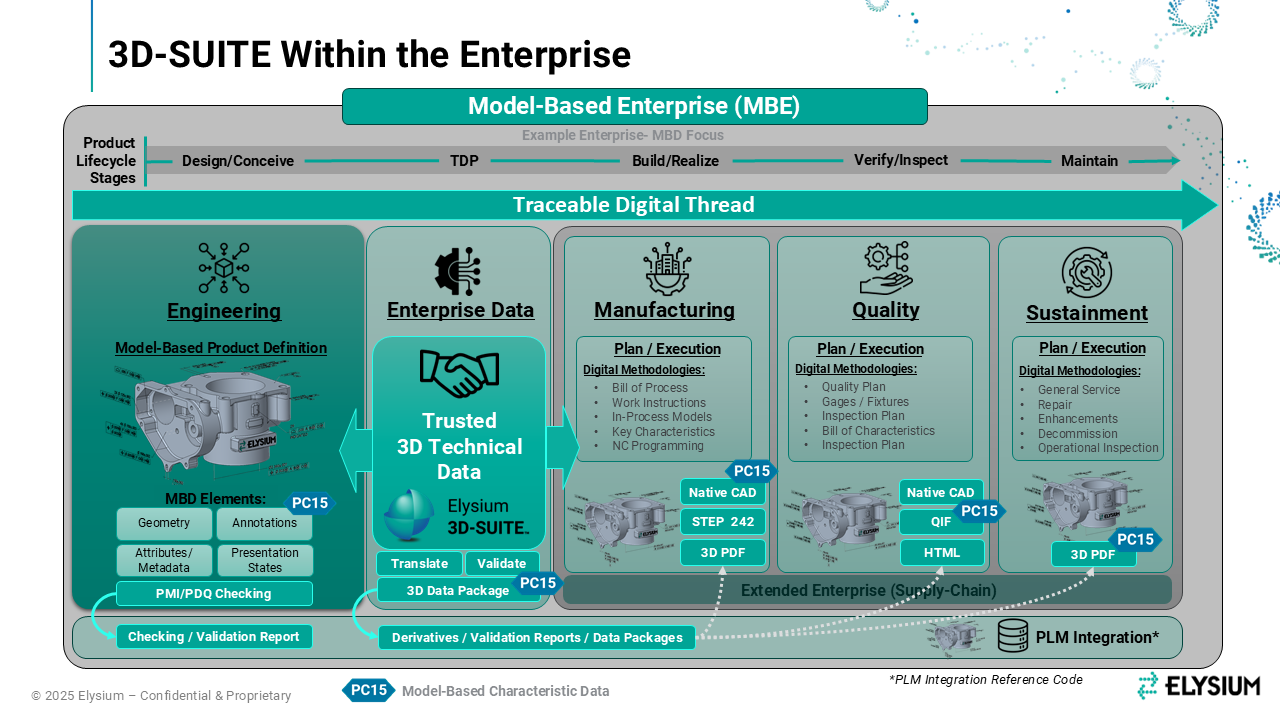
A model-based enterprise uses digital methodologies as the foundation for deploying products from concept to disposal. These methodologies can be understood as model-based digital capabilities. The MBE maturity index identifies many of these capabilities at the facet level, and Elysium supports many of them through tools evaluated against the index. The central goal is to leverage and exchange model-based definition data across the enterprise.
This is focused on model-based definition, though I realize that many kinds of data are being created and exchanged across an enterprise.
Why MBD Quality Matters
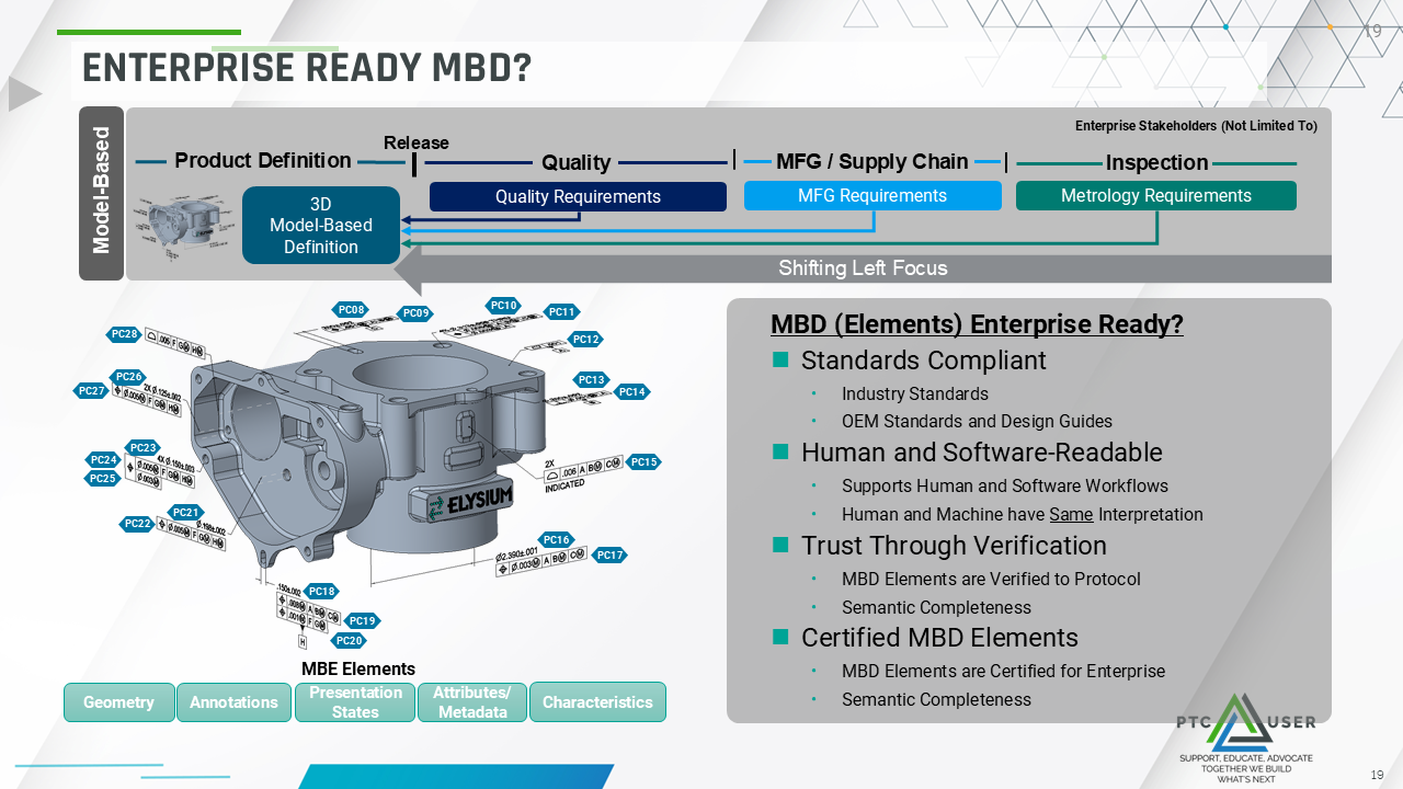
To support enterprise consumption, MBD data must be standards-compliant, aligned with OEM standards or internal design guides, usable by both human and software workflows, and trusted through verification or certification. These needs are also being addressed within ASME standards, because the MBE maturity index identifies the importance of these capabilities, while standardized implementation methods are still evolving.
Right or wrong, I think that’s up to your own policies. But how can we ensure that this data is ready for enterprise consumption? That it’s standard-compliant to industry standards, your own OEM standards or design guides, that it supports human and software workflows within your enterprise, and that it’s trusted through some type of verification protocol and certification. These are things that we’re trying to solve even within ASME standards because the MBE maturity index calls out these types of capabilities, but we don’t yet have a good set of standards to do it in a standardized way, which is important.
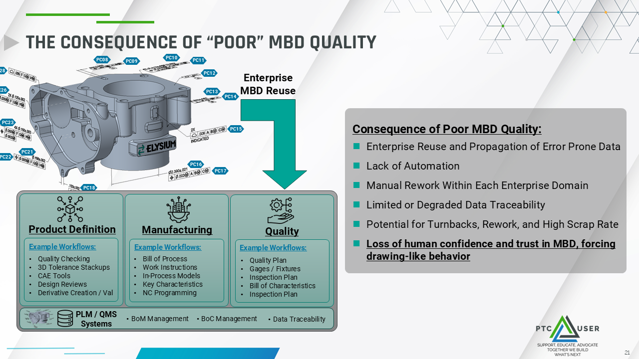
Model-based definition supports many consumption workflows across the enterprise. In engineering, it enables quality checking, onboarding of specific quality checking tools, 3D tolerance stack up analysis, computer-aided engineering, design reviews, derivative creation, and derivative validation. In manufacturing, it supports bills of process, 3D work instructions, and NC programming. In quality, it supports quality planning, bills of characteristics, and inspection plans. These workflows can be driven automatically from model-based definition, with data stored in PLM and quality management systems to improve traceability.
Because MBD supports so many workflows, feedback must be provided upfront. Poor MBD quality can propagate error-prone data across the enterprise, reduce automation, create manual rework, weaken data traceability, and increase the likelihood of turn backs, rework, and scrap. The greatest risk is a loss of trust in model-based definition, which can cause teams to return to drawing-like behaviors.
The Consequences of Poor MBD Quality
Each element of MBD has distinct quality risks. Enterprise reuse workflows may rely on only a subset of MBD elements, so poor quality in any one area can affect downstream consumption.
Poor geometry quality can result in unstable or fragile models that are not watertight. Downstream users may fix these issues locally, breaking the digital thread. Poor annotation quality can lead to incorrect, noncompliant, or semantically incomplete product definition, which can mislead consumption-domain decisions and create significant risk.
Presentation states are more qualitative than quantitative. Y14.5 says that product definition should be authored in a way that maximizes readability. When you do that through model-based definition, you’re forced to author product definition one view at a time. This is somewhat subjective, but not doing it correctly, or not following your own internal standards, could cause downstream users to miss critical requirements. If data is not marked as published, it will not get published out to downstream consumers. If view naming does not follow your internal nomenclature, you may have a difficult time sorting that data downstream the way you intended.
Attributes and metadata affect all MBD elements. Because they are the backbone of machine readability, they must be correct to ensure that human interpretation and machine interpretation remain consistent within consumption workflows.
Product Data Quality Checking with 3D Model-Based Data
Elysium helps customers create trusted 3D model-based definition data through dedicated quality checking for geometry, PMI, and design for manufacturability. These capabilities support geometry validation, PMI validation, and manufacturing-focused checks, with PMI checking receiving particular emphasis.
Elysium’s geometry checking capabilities can identify tiny edges, gaps, and missing faces. The tools can be configured for compliance with industry standards such as Military Standard 31000, customer-specific standards, or internal best practices. During translation from Creo to QIF, STEP, JT, or another target CAD system, healing can be performed to ensure the data is watertight.
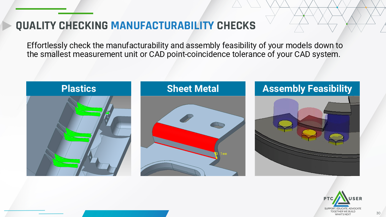
For design for manufacturability, Elysium provides manufacturing feedback in engineering. These checks are customizable and support plastic injection molded parts, sheet metal, and assembly feasibility, with the assembly checks currently focused on fasteners. Examples include checks for holes, ribs, potential sink marks, draft angles, axial misalignment, axial engagement, and fastener accessibility for wrench or socket removal.
PMI Checker: Validating Product Manufacturing Information Upfront
PMI Checker, released within EX11 last year, is an automated tool that validates the accuracy, standards compliance, and semantic completeness of product manufacturing information within an MBD model. It is designed to run upfront in the engineering domain, or wherever model-based definition data is created and released, so issues can be identified before the data reaches consumption domains.
PMI Checker includes 36 checks across five categories: general checks that affect all PMI types within Creo, dimensions, datums, GD&T, and geometry. It is compliant with current industry standards, including ISO 1101, ASME Y14.5, and ASME Y14.41. While some checks overlap with Creo Parametric capabilities, PMI Checker extends those capabilities by providing upfront feedback that helps ensure data is fit for downstream use.
Some of the easier checks identify PMI that has no surfaces associated with it, PMI that is only associated with edges or vertices, and PMI associated with supplemental geometry such as axes, planes, points, curves, or sketches. One of my favorite checks is quantity mismatch. With feature recognition, we can read the pattern syntax and associated objects to make sure the expected number of cylindrical features is associated with all stacked items in the stack.
For dimensions, we can ensure that the nominal value and the actual associated objects match. We can identify untoleranced dimensions and nominal value mismatches within a pattern. It is easy to collect things in Creo, but it is also easy to collect something that is not the same nominal size and send it downstream. PMI Checker ensures that all nominal values within a pattern match within a specific threshold, and it can also identify nominal value mismatches caused by rounding when tolerances are very tight.
For datums, Creo already does a strong job of checking, but PMI Checker goes further. If a datum is used within a feature control frame but is not explicitly called out in the model, the tool can flag it and prompt the user to identify it. It can also check against Y14.5 concepts by ensuring that datums are related to higher-ranking datums in a way that makes sense for downstream metrology. It can also identify datum features that do not have tolerances, which is important because datums need to be qualified downstream in metrology.
For geometric tolerances, the tool checks whether the applied geometric characteristics and feature type match and are compatible with each other. It can check between symbols by identifying surfaces that should be continuous and flagging any break in continuity. It can also identify simple issues such as a missing diameter symbol on a cylindrical feature of size or suggest when an all-around symbol should be used for an all-around profile feature. Finally, untoleranced surface detection can show all features in the model that do not have an associated tolerance, using a color-coded view that makes issues easy to find and correct in real time.
There are two primary ways to interact with PMI Checker. The first is an interactive viewer synchronized with Creo and a 3D PDF. PMI Checker can be run directly from a Creo Parametric plug-in, and the results can be opened in Inspector and Model Viewer. The viewer synchronizes with Creo Parametric in orientation and zoom, and the results are served by presentation state so users can follow along within Creo. Each view shows PMI Checker categories and a quick scorecard of failures, warnings, and passes.
When a category is selected, the tool shows the initial result and evaluation. If an issue is corrected in Creo, the result can be marked for update so the analysis can be rerun. For example, a composite tolerance may have a quantity mismatch where stacked items do not match. The user can correct the missing feature association in Creo, mark the result as pending update in PMI Checker, and continue through the views until all issues in the tool have been satisfied.
The second way is through a 3D PDF. The data is presented in a similar way, but everything is contained within the 3D PDF, including a scorecard at the top and access to all presentation states. Users can filter specifically for failures or warnings, select a view, and see all PMI within that view, along with a mini scorecard of failures and warnings. Selecting a result explains the failure, while the user makes the correction in Creo in real time. There is also a roadmap for PMI healing with consent, where the system could detect an issue, ask the user whether to fix it, and then apply specific corrections.

Building Data Traceability with Model-Based Characteristics and QIF
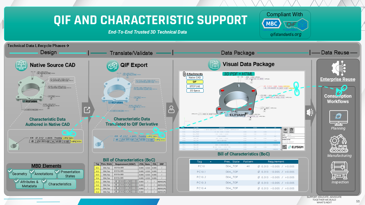
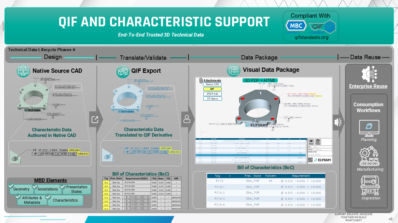
Data traceability with model-based characteristics and QIF begins with data in Creo Parametric, whether characterized or uncharacterized. That data is translated to QIF, while JT, STEP, and other major neutral and standard formats are also supported. A QIF-based data package can then create a visual and interactive bill of characteristics for downstream consumption domains.
QIF, or the Quality Information Framework, is a standard neutral format developed by the DMSC and recognized as an ISO standard. It is feature-based and characteristic-centric, carrying key MBD elements such as geometry, PMI, attributes, and presentation states. Current versions include QIF 2.1 and QIF 3.0, with QIF 4.0 in development.
The next topic is model-based characteristics. According to the Model-Based Characteristics 1.0 standard, there are two types of tags. The first is a product characteristic tag, which applies to each requirement within the MBD model. Each dimension and tolerance receives a parent tag. The second is an instance tag. For example, in a pattern of four holes with a size dimension and position tolerance, each hole receives an instance tag for each requirement.
A bill of characteristics can then be generated. Traditionally, this is something a person does downstream when ballooning or bubbling a drawing, but now it can be done automatically. Third-party tools can generate characteristic tags within Creo, and if those tags exist in Creo Parametric, they can be translated. The DMSC Model-Based Characteristics 1.0 standard, along with the QIF standard, is available as a free download from qifstandards.org.
When exporting to QIF from Creo Parametric, the source data may be uncharacterized, which is common for model-based definition. Even if characteristics are not yet present in the MBD data, 3D-SUITE can export and translate to QIF by harvesting the geometry and all annotations across presentation states. During the QIF export process, it can create product characteristic tags and instance tags, generating a bill of characteristics directly within the QIF file. There is also flexibility in tag prefixes, such as PC1 or PC001.
If the MBD data is already characterized, that data can also be translated. The same process harvests the geometry and annotations, but now it reuses the characteristic tags authored in native Creo. Instance tags often do not exist yet, which is one of the more difficult aspects of characterizing data in a native CAD system. In that case, the parent tag can be reused, and missing characteristics can be supplemented or augmented to generate the bill of characteristics.
The data can also be validated. Characteristic tags that exist in the native CAD data can be checked for persistence when translated into QIF, ensuring that the information remains intact. Even without native characteristic tags, the QIF file can be validated back to the source CAD data.
Creating Interactive Bills of Characteristics for Downstream Use
Next is a 3D PDF bill of characteristics, which can function as a quality data package or any other type of data package because a 3D PDF can include attachments. The package includes a large bill of characteristics with detailed information, access to all views within the MBD model, quick access to general notes, and optional template customization. It can also include attachments such as QIF, STEP, JT, native Creo data, or quality documents that need to be communicated downstream.
The key element is the bill of characteristics table. It includes characteristic tags, the presentation state where each requirement resides, whether the requirement is part of a pattern, and the requirement itself. It can also show a requirement breakdown with total tolerance, nominal value, plus tolerance, and minus tolerance. In this example, the 3D PDF is visualizing QIF data, and the characteristic tags come from the QIF file rather than native Creo.
The 3D PDF is interactive. When PMI is selected in the graphics display window, especially for a pattern, the table can expand to show instance tags without making the table unnecessarily long for large patterns. The instance tags are mapped directly to their features, allowing users to understand the relationship between requirements and the model geometry.
Quality planning forms are also supported. Bill of characteristics data can be extracted from the QIF file and exported directly to Excel. Out of the box, the system supports AS9102 and FAIR forms, and users can manage their own templates by mapping data to specific columns. This makes the 3D PDF and exported forms a decoder ring between QIF data and downstream quality and metrology workflows, helping users understand how instance tags map to actual features within the model. The workflow demonstrates a digital thread from Creo Parametric into QIF and into a downstream data package.