

Alexander Christ, Elysium Europe S.A.R.L.
High-fidelity translation of 3D product data and appropriate validation technologies are the essential key factors for increasing digitalization of products as well as the step toward a closed-loop lifecycle. Each of these key factors allow organizations to meet future business and engineering requirements. Starting with the definition of requirements up to the delivery of the final product, validation is the key enabler to analyze developed solutions and to ensure product data quality throughout the entire product creation process. Depending on the use cases and risk assessment, different levels of validation accuracy are needed. Validation technology itself is applied at various stages of product development, e.g., virtual validation of 3D models or physical validation of component prototypes [9]. The utilization of automated validation solutions opens up a huge potential for cost savings, risk reduction, and improvement of interoperability in collaborative product development.
What Is Validation and Why Is It Important
The definition of the term validation and its scope highly depends on the application area. For validation of 3D CAD models, the definition of the Institute of Electrical and Electronics Engineers (IEEE) can be taken into consideration: Validation is the process of evaluating a system or a component during or at the end of the development process to ensure that the production specification has been fulfilled [3]. Validation is to analyze if the right thing has been done correctly through the comparison of 3D CAD models. This allows the comparison of 3D CAD models.
Validation of 3D CAD Models
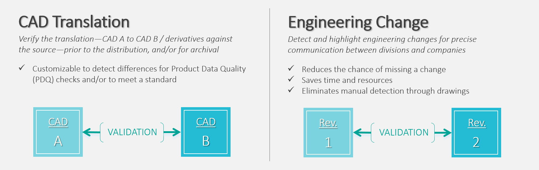
For the application of validation technology in 3D engineering, two major use cases can be distinguished: Detection of errors after CAD translation and documentation of engineering changes.
CAD Translation: After the translation of a 3D CAD model, users need to make sure that the new 3D CAD model matches the old one. Ideally, for further processing both 3D CAD models should be identical. All translation errors should be identified when translating a 3D CAD model into different CAD formats; such as industry standards like STEP (Standard for the Exchange of Product Model Data) [1] and JT [4], or even different versions of the same CAD system. Translation errors mainly result from differences in mathematical kernels for geometry definition, different methods used in creating 3D models, and the level of interpretation related to import and export of CAD formats [7]. It is of high importance to detect significant changes to ensure product data quality for all downstream processes, as undetected errors could result in loss of production.
Engineering Change: In collaborative product development, 3D CAD models are shared between different departments of one company as well as with external partners and suppliers. In the design process, modifications for innovation are repeated, which means new revisions of existing 3D CAD models are created daily. Contrary to translation errors, these changes of 3D CAD models are intended. Still, they have to be detected and reported in a suitable manner. The knowledge of engineering changes has to be documented and shared within the collaborative development environment, otherwise, undocumented engineering changes become a bottleneck to track and identify.
Use Cases for Validation
In a nutshell, validation in 3D engineering allows users to identify what has been changed in their 3D CAD models, intentionally or inadvertently. Besides 3D geometry, validation technology also enables the analysis of assembly structures, tolerances, attributes and semantic PMI (Product and Manufacturing Information). The objectives are a 100 percent accurate statement on product data quality, and to ensure the reliability of the results.
Challenges in Manual Validation
In production industries, validation is often conducted manually, costing engineer’s months to compare CAD models on 3D geometry and semantic PMI by visual inspection. Manual validation after CAD translation or engineering changes is not efficient. On one hand, clear statements are usually impossible. Just imagine a visual inspection of a whole engine block. With manual validation, users cannot guarantee that all changes have been detected. Even if all changes have been detected by visual inspection, the significant changes are often buried in noise. On the other hand, engineers that are forced to conduct a manual validation of 3D CAD models lose motivation after around two hours at the latest. This implies a high risk of error that is not acceptable as undetected validation errors can negatively affect all stages of product lifecycle [2]. Moreover, cost pressure, increasing quality requirements, and complexity of engineering processes demand efficient computer-aided methods and tools for validation. Deploying computer-aided validation will contribute to not only significantly improve the efficiency while eliminating the risk of misdetections, but also to bring the communication via 3D CAD models to the next level of preciseness.
Major challenges in today’s world of engineering are to keep track of engineering changes within collaborative development environments and to estimate the monetary value of the applied engineering changes. Especially in supplier integration in the automotive industry with multi-tier supply chains, a precise calculation of costs based on the real amount and effort of engineering changes is needed. Validation technology contributes to this topic as it enables the precise comparison of 3D CAD models and the monitoring of all changes applied. As enriched 3D CAD models are operationalized throughout all downstream processes, efficient solutions for validation and sharing of information with all involved stakeholders are needed [6].
Solution Approach: Automated Validation with Elysium’s ASFALIS
A highly promising approach to increase efficiency is the automation of validation tasks. As 3D CAD models already provide a digital representation of a product or a component, computer-aided tools and methods can be applied. Target scenarios are assurance of data equivalence and the identification of engineering changes. The first target scenario includes supplier data exchange (CAD-to-CAD translation), translation for downstream processes, long-term archiving and retrieval (LOTAR), CAD migration and CAD version upgrade. The second target scenario includes identification of changes in engineering change orders (ECO) and between PLM revisions of a model. The objectives are to automatically confirm equivalence of translated data to the master data, detect significant differences, and filter out differences that are not relevant to the engineering change [6].
Mechanism of Comparison [6]
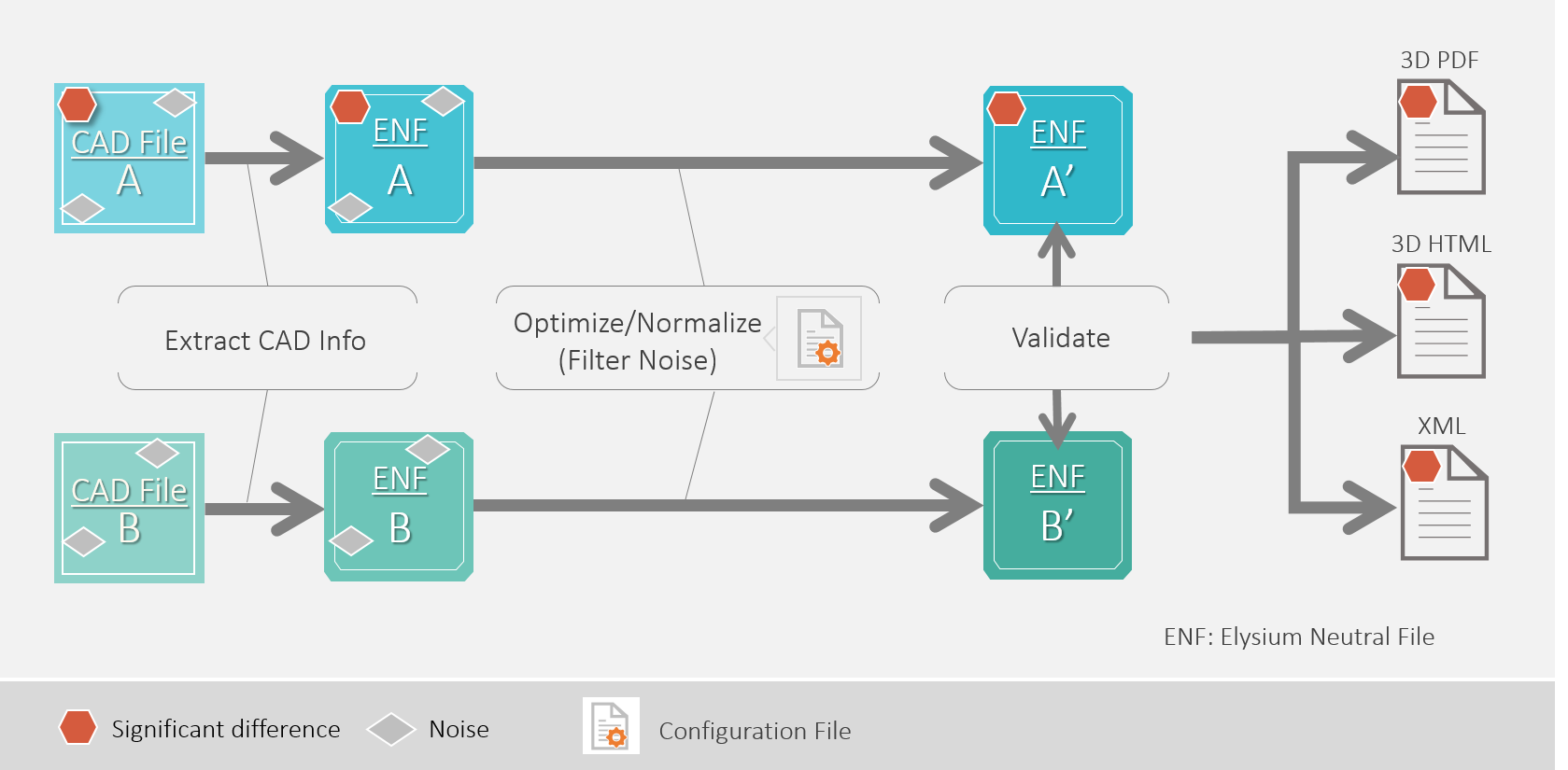
The mechanism of comparison is to export the 3D CAD models to an intermediate file format—rich container format to store all data extracted from the source CAD file using the API (Application Programing Interface) provided by CAD vendors under the official partnership, which allows high-fidelity data transfer of both geometry and non-geometry information—and then compare the normalized representations. Based on this comparison with normalized representations a validation report is created. This mechanism can be applied to all validation scenarios, but significant differences often get buried in noise. With Elysium’s ASFALIS solution for validation the 3D CAD models are normalized and optimized before comparison to filter out noises. For the normalization and optimization of the 3D CAD models, configuration files are deployed. These configuration files are highly customizable and consider specifications of CAD systems and translators. This allows to cater to the specific needs of validation users in order to report only the significant differences [6].
Smart and Intuitive Reporting
Smooth processing, documentation and communication of changes, and smart and intuitive reporting is desired by users. Elysium’s validation technology enables the utilization of different formats for validation reports. Based on ASFALIS, validation reports can be created as 3D PDF, 3D HTML and XML. While formats like 3D PDF and 3D HTML maintain readability of validation reports by humans, XML provides a machine-readable format to enable syntactical and semantic interoperability.
3D PDF and 3D HTML validation reports are highly adaptable to fulfill users’ needs. They contain a graphical presentation of the two 3D CAD models that have been compared. This allows users to interact with the 3D CAD models via functions to pan, rotate and zoom in and out. 3D annotations like dimensions, tolerances and PMI are also available in the graphical presentation. For PMI, not only are the polylines captured, but also the semantic information is as well. Besides, a textual presentation of differences between assembly structures, system attributes and user attributes are accessible. Templates enable the flexible customization and reuse of validation reports.
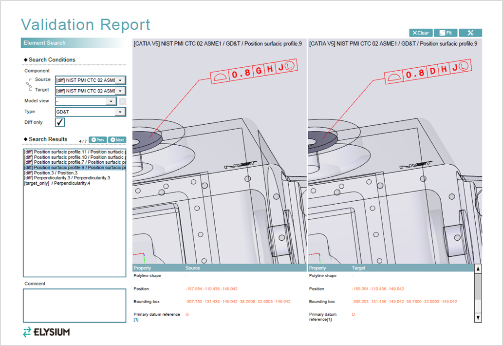
Validation Report as 3D PDF
All validation reports from Elysium can be utilized in various downstream processes such as production planning, manufacturing, quality, assurance and many others. Depending on their business strategy, companies may follow a file-based approach with 3D PDF or a mobile approach utilizing HTML validation reports on different (mobile) devices. As Elysium’s validation reports are independent of any specific CAD system, they can reach a wide audience. By utilizing validation reports companies have the ability to see a major return on investment as CAD licenses and user training is not required.
Conclusion
Elysium’s validation technology contributes to the general significance of validation throughout the whole product creation process, while simultaneously fulfilling individual user demand. Compared to manual validation with mainly visual inspection, automated validation can save engineers months of time, and avoid unnecessary rework by automatic, accurate, and complete validation. Hence, it is a key enabler for tasks that cannot be performed manually, bulk data processing, and validation by casual users [2]. The validation reports provide a self-contained documentation of changes applied to 3D CAD models with a high level of detail in regard to 3D geometry, PMI (polyline/semantic), attributes, and assembly structures. Based on Elysium’s ASFALIS platform, data is automatically validated and distributed as validation report. This enables a fully automated validation solution with a high throughput. Due to the support of several formats for validation reports (3D PDF, 3D HTML and XML) a future-proof solution for different business strategies (file-based vs. mobile) can be achieved. Users can easily and flexibly customize their validation processes and reports.
As a next development step, a more suitable integration of validation reports into 3D PDF is desired. Following approaches like the Technical Data Package (TDP) [5] or drawing-free product documentation (Produktdokumentation in einem Zeichnungslosen Prozess, ZLP) from German Association of the Automotive Industry (VDA) [8], the 3D PDF will be utilized as a container for 3D data and beyond. Major enhancement includes the addition of files (XML, Office documents, 3D CAD models etc.) to the 3D PDF as attachments that can be directly accessed. Users can store all data needed for validation in one TDP rather than searching for it in different system, this then allows users to utilize this information in several downstream processes out of one single source. The TDP enables the distribution of validation reports and corresponding data to all stakeholders for a smooth, efficient and precise communication. This implies a huge opportunity for further cost savings, time reduction, and improvement of interoperability.
Literature
[1] Anderl, R.; Trippner, D. (2000): STEP. Standard for the Exchange of Product Model Data. Eine Einführung in die Entwicklung, Implementierung und industrielle Nutzung der Normenreihe ISO 10303, Teubner, Stuttgart, Germany.
[2] Christ, A.; Biedert, J. (2017): Automated Validation of 3D Geometry and Semantic PMI at Daimler. EDM CAE Forum 2017, Stuttgart, Germany.
[3] Institute of Electrical and Electronics Engineers (2000): The Authoritative Dictionary of IEEE Standard Terms, Seventh Edition. IEEE 100, New York, NY, USA.
[4] International Organization for Standardization (2012): Industrial Automation Systems and Integration – JT File Format Specification for 3D Visualization. ISO 14306:2012.
[5] McFeeters, J.; Spreier, P. (2016): Best Practices for Creating Technical Data Packages (TDP) using 3D PDF and STEP AP242. Global Product Data Interoperability Summit (GPDIS) 2016, Phoenix, AZ, USA.
[6] Sagawa, Y. (2016): ASFALIS Geometry Validator. Elysium Partner Summit 2016, Hamamatsu, Japan.
[7] Suzuki, A.; Herron, J. (2016): CADValidator – A Critical Aid for the Model-Based Enterprise. Elysium white paper, Southfield, MI, USA.
[8] Verband der Automobilindustrie e.V. (2014): Drawing-free Product Documentation. VDA Recommendation 4953-2, VDA, Berlin, Germany.
[9] Verein Deutscher Ingenieure (2004): Design Methodology for Mechatronic Systems. VDI-Richtlinie, VDI 2206, Beuth, Berlin, Germany.